
Resiliency Impact of Circulating Current Suppression for Parallel Connected Inverters in Microgrid
By Shamsul Aizam Zulkifli, Mubashir Hayat Khan
The impact of the circulating current at a localized Microgrid is severe to the voltage, phase, and frequency at the inverter outputs and may lead to system failure. Each Distributed Generator (DG) has different impedance types such as resistive impedance or inductive impedance which create different amounts of circulating current and new current flow paths inside the inverter. Circulating currents reduce the efficiency of power flow between the inverter and the Point of Connection (PCC). The most severe impact of the circulating current is at parallel inverters network due to line impedance mismatch.
With ‘N’ number of inverters connected to the same PCC with different line impedances, there is an increase in the difference of circulating current flowing to each inverter. Although DG inverter is an intelligent system with smart control capabilities, it faces challenges due to different rated power output connected to the same PCC. This configuration also causes circulating current suppression inside the inverter to be more uncontrollable. In the meantime, the voltage level between the inverter and PCC should be maintained to make sure current flows from high potential to low potential DG with the help of line impedance on the inverter connection. Generation of equal power sharing for two level inverters in the control system with the equal line impedance for both DG can be determined by implementing a droop control mechanism. The droop control is suitable when the DG line impedances are the same value and type and is less effective when the line impedance and type are different.
Therefore, an improvement of the droop control is achieved by adding the virtual impedance control model to the droop controller to mitigate circulating current generation. It also enables accurate power sharing when additional inverters with different rated power are connected to the PCC. Figure 1 shows the parallel connection of DG1, DG2, up to DGN and the line impedances are shown as Zline1, Zline2……ZlineN while iH1,iH2,…..iHN are the currents flows to each inverter.
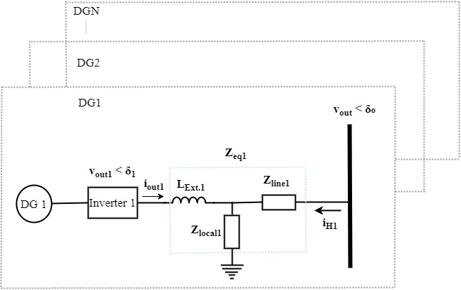
Figure 1. Microgrid system with N DG inverters
Several solutions can be applied to mitigate this circulating current as given as iH1. One of the solutions is the use of angle droop control to regulate frequency and Q-V and P-f droop control for the voltage regulation. Moreover, to suppress circulating currents, a control mechanism for parallel connected inverter control is proposed. It can also be implemented in DG inverter, as shown in Figure 2. Where, iH1, is the input to h(iH) ,the variable which depends on the virtual limit with a delay block 1/s is used to calculate the change in circulating current within a short period of time │∆iH │. This time can be determined based on fault time response. The proposed technique includes virtual impedance values at ZD, where the values are calculated from small signal stability analysis based on line inductance and output currents iodq at dq-frame for the reference voltage signal. Changes in circulating current by varying virtual impedance error values with specific boundary impedance level is constantly measured and treated accordingly. By limiting the permitted circulating current to 1% of the rated current, or when the circulating current is < 1%, the judgemental variable h (iH) can adjust itself to zero so the virtual impedance value will not be changed and will not affect the control dynamic. If the value of permitted circulating current is greater than 1%, i.e. exceeding the permitted value, then the virtual impedance value change itself accordingly to nullify the effect of circulating current. This control scheme is explained in Figure 2, and can reduce the circulating current in DGs with different rated line impedances. Moreover, deviations in the iH1 values caused by the sudden change in load power which should also be adjustable to behave as adaptive virtual impedance. Adaptive virtual impedance is reflected to control impedance boundary that can be self-adjusted based on feeder impedance and power deviation for the line, while considering the circulating current values and its changes. The circulating current produced due to line impedance mismatch is mitigated within the Microgrid system using the proposed control strategy. In conclusion, the power sharing accuracy as per the capacity of the connected DG is also improved by implementing the proposed technique without compromising the power quality and stability of the system.
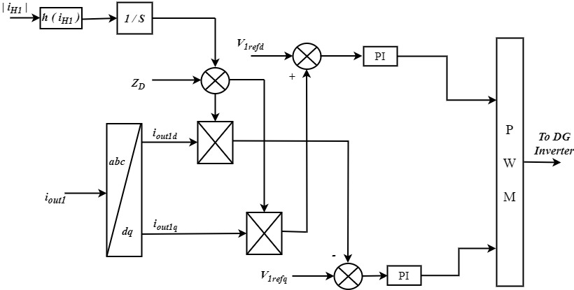
Figure 2. Circulating current Control with Adaptive virtual impedance
This article edited by Hossam Gabber
For a downloadable copy of the September 2020 eNewsletter which includes this article, please visit the IEEE Smart Grid Resource Center.


To have the Bulletin delivered monthly to your inbox, join the IEEE Smart Grid Community.
Past Issues
To view archived articles, and issues, which deliver rich insight into the forces shaping the future of the smart grid. Older Bulletins (formerly eNewsletter) can be found here. To download full issues, visit the publications section of the IEEE Smart Grid Resource Center.
IEEE Smart Grid Bulletin Editors

Managing Editor

Assistant Managing Editor

Interim Managing Editor
IEEE Smart Grid Publications Editorial Board
Mehdi Moghadasi
Mehmet Cintuglu
Geev Mokryani
Jose Medina
Merhrdad Boloorchi
Vigna Kumaran
Hossam Gaber
Jorge Angarita
Ali Nabavi
Vijay Sood
Julio Usaola
Cesar Duarte
Gabriel Ordoñez
Jorge Martinez
Jenny Zhou
Click here for more info
Dr. Panayiotis (Panos) Moutis
Editor-in-Chief
IEEE Smart Grid Bulletin