
Deployment Strategies of Fast Charging Stations with Microgrids
Written by Hossam A. Gabbar
The world is moving towards fast-charging stations to support transportation electrification and mobility requirements. The deployment of fast charging infrastructures faces several challenges. This paper analyzes deployment strategies and design scenarios of fast charging stations as integrated with microgrids. Integrating nuclear-renewable hybrid energy systems in large-scale fast-charging stations for buses, trucks, and maritime transportation is essential to meet charging loads and demand profiles. Requirements analysis is presented in view of different deployment strategies considering mobility demands and target performance measures. Different design configurations and control strategies are discussed with possible deployment planning and operation.
Introduction
In view of climate change mandates, several initiatives are aiming to reduce greenhouse gas (GHG) emissions. Transportation electrification is a vital strategy to reduce GHG emissions from the transportation sector. Community development has led to higher mobility demands and increased goods movement, which require an increase in charging infrastructure capacity with reduced charging time and costs. The recent development of fast charging and ultra-fast charging proved practical implementations in different regions and communities worldwide. Transportation electrification includes electric vehicles (EVs), electric buses (EBs), electric trucks (ETs), electric maritime (EMs), and other lightweight transportation systems such as electric bikes and electric scooters. DC fast charging and ultra-fast charging technologies are progressing steadily with enhanced features to support different transportation systems. Infrastructure planning is based on mobility demands and grid conditions [1]. The cost models for fast and ultra-fast charging should be competitive to meet all views from transit companies, municipalities, utilities, end-user, and transportation electrification technology providers. These requirements are translated into feasible and practical designs of fast-charging stations. Fast charging causes higher loads on the grid, especially during peak hours [2]. Therefore, fast charging stations should be supported by local energy supply sources within the charging station [3]. This paper discusses possible design configurations of fast-charging stations with microgrid.
Fast Charging Station Design
The design of fast charging station is based on integrating renewable energy sources, such as PV and wind turbine (WT), where their intermittent generation can be balanced with energy storage. Hybrid energy storage can improve the performance with different energy and power density technologies such as battery (BT), ultra-capacitor (UC), and flywheel (FW). With the high charging demands for EVs, EBs, ETs, and EMs, small-scale PV and WT are insufficient to support fast charging for regions and communities. Micro modular reactors (MMR) are small-scale nuclear reactors that are developed to support energy supply for remote areas, different communities, and maritime [4]. The integration of MMR as a nuclear reactor (NR) will support high charging demands for fast charging infrastructures. The interface between PV to the DC line is via DC-DC converter. WT is linked to DC line via AC-DC converter. The grid interface to the DC line is via AC-DC converter. NR is integrated with the DC line via AC-DC converter. Energy storage of battery (BT) and ultra-capacitor (UC) are integrated via a multi-input DC-DC converter. Flywheel (FW) is integrated via AC-DC converter. Controllers are used to controlling connections with each energy resource. PV-C is the PV controller, WT-C is the wind turbine controller, GR-C is the grid controller, NR-C is the nuclear reactor controller, ES is the energy storage controller for both battery (BT) and ultra-capacitor (UC). FW-C is the controller of the flywheel. Supervisory controller (FCS-SC) is used as the integrated controller for the fast charging station. A controller is used with each charging unit to control the charging process based on incoming charging load, microgrid capacity, and grid condition. FCS-C1, FCS-C2, and FCS-C3 are the controllers for each charging unit. Energy management is achieved by communicating incoming buses, vehicles, trucks, and maritime energy management strategies. TEMS-T is the truck energy management system within the truck and used to plan ETs charging demand profiles based on nearest charging stations, mobility requirements, and trip model.
Similarly, BEMS-B is the energy management system within the bus. VEMS-V is the vehicle energy management system from the vehicle side. TEMS-T coordinates wirelessly with the truck energy management system in the station side. All incoming trucks will interface with TEMS-S in the station side. Similarly, BEMS-S will manage requests from all incoming buses via wireless connections between BEMS-B and BEMS-S. VEMS-S will coordinate with VEMS-V from all incoming vehicle to coordinate charging loads for EVs.
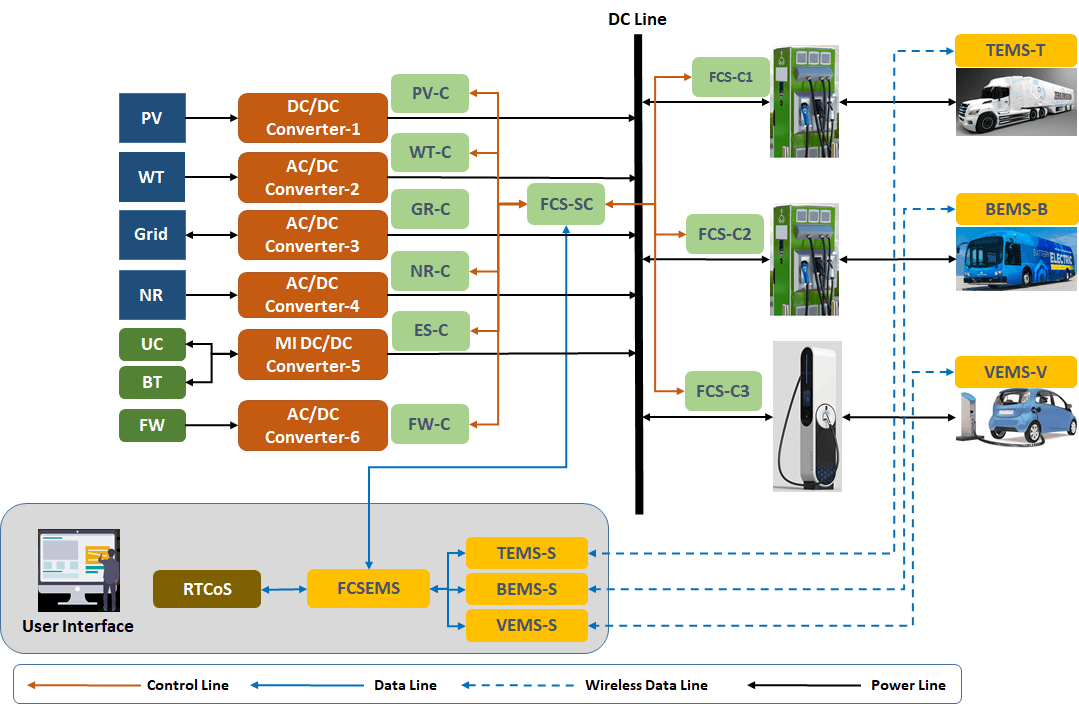
Fig. 1: Design of a Fast Charging Station with Microgrid
The integrated energy management system for the FCS is known as FCSEMS, which is interfaces with TEMS-S, BEMS-S, and VEMS-S. Real-time co-simulation is used to evaluate different control and operation scenarios and parameters and tune the operation of the FCS accordingly. The user interface supports FCS operations' monitoring, control, and planning. The design configuration of the integrated fast-charging station is shown in Fig. 1, where power lines, control lines, data lines, and wireless lines are used in the design schematic.
Resilient Control of Fast Charging Station
There are situations where challenging conditions will cause difficulties to the fast charging station's operation. Heavy snow might make it difficult for incoming vehicles to reach charging units. Very high charging demand might make it difficult to fulfill all incoming charging requests. Protection systems are in place to protect hazardous situations for each component, such as high current, high voltage, or fire again. The resiliency functions are different from protection layers and will be implemented within each controller. Resiliency control functions are implemented within each controller to achieve suitable resolutions based on internal and external factors, FCS conditions, and incoming charging loads. Resiliency layers can be implemented on the design or operation side. On the design side, larger energy storage compensates for lower grid supply or higher charging load. In the operation stage, load following the control strategy of the nuclear reactor will enable a higher energy supply for high incoming charging loads. A probabilistic approach quantifies the resiliency demand scenarios and evaluates the potential resiliency layer in the design and operation parameters.
Deployment Strategies of Fast Charging Station
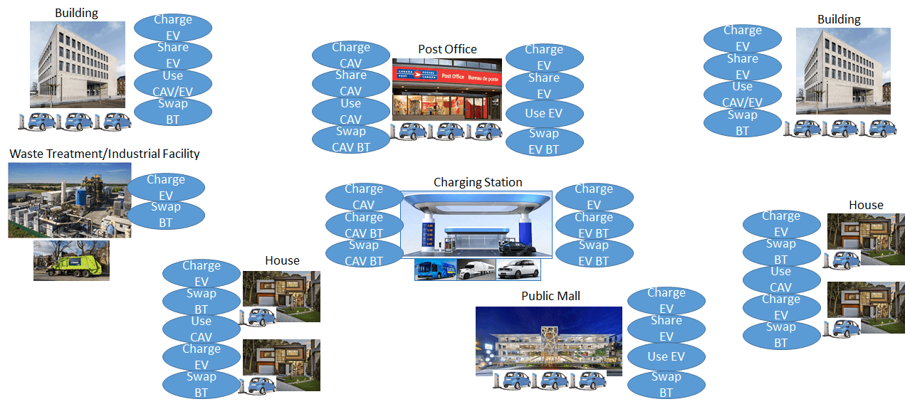
Fig. 2: Deployment Strategies of Fast Charging Infrastructure
The deployment of fast charging is based on mobility demand profiles, community planning, and technology development. The recent development of connected and autonomous vehicles (CAV) has led to additional requirements to be incorporated in the design of fast charging infrastructures to support driverless cars. Also, the mobility business model could be changed based on technology development. Flying cars are examples of recent transportation technology development [5], which will require analysis on charging load impacts on the fast charging station and the grid.
Fig. 2 shows possible deployment strategies for fast charging infrastructures based on utility substation distribution, industrial facilities, distribution centers, mobility requirements, business models, and transportation technology development.The post office example is used to show a possible share of EV/CAV, charging EV/CAV, or swapping the battery in EV/CAV. A charging station could be located beside a utility substation, industrial facility, or maritime seaport to support EVs, EBs, ETs, or EMs.
References
- Burnham, Andrew; Dufek, Eric J; Stephens, Thomas; Francfort, James; Michelbacher, Christopher; Carlson, Richard B; Zhang, Jiucai; Vijayagopal, Ram; Dias, Fernando; Mohanpurkar, Manish; Scoffield, Don; Hardy, Keith; Shirk, Matthew; Hovsapian, Rob; Ahmed, Shabbir; Bloom, Ira; Jansen, Andrew N; Keyser, Matthew; Kreuzer, Cory; Markel, Anthony; Meintz, Andrew; Pesaran, Ahmad; Tanim, Tanvir R, Enabling fast charging – Infrastructure and Economic Considerations, Journal of Power Sources, 2017-11-01, Vol.367 (C), p.237-249.
- A. D. Clarke, E. B. Makram et al., “An innovative approach in balancing real power using plug in hybrid electric vehicles,” Journal of Power and Energy Engineering, vol. 2, no. 10, p. 1, 2014.
- H. J. Vermaak and K. Kusakana, “Design of a photovoltaic–wind charging station for small electric tuk–tuk in dr congo,” Renewable energy, vol. 67, pp. 40–45, 2014.
- Gabbar, Hossam A; Adham, Md. Ibrahim; Abdussami, Muhammad R, Analysis of nuclear-renewable hybrid energy system for marine ships, Energy Reports, 2021-11, Vol.7, p.2398-2417.
- Kasliwal, Akshat; Furbush, Noah J; Gawron, James H; McBride, James R; Wallington, Timothy J; De Kleine, Robert D; Kim, Hyung Chul; Keoleian, Gregory A, Role of flying cars in sustainable mobility, Nature Communications, 2019-04-09, Vol.10 (1), p.1555-1555.
This article edited by Geev Mokryani.
To view all articles in this issue, please go to March 2022 eBulletin. For a downloadable copy, please visit the IEEE Smart Grid Resource Center.

To have the Bulletin delivered monthly to your inbox, join the IEEE Smart Grid Community.
Past Issues
To view archived articles, and issues, which deliver rich insight into the forces shaping the future of the smart grid. Older Bulletins (formerly eNewsletter) can be found here. To download full issues, visit the publications section of the IEEE Smart Grid Resource Center.
IEEE Smart Grid Bulletin Editors

Managing Editor

Assistant Managing Editor

Interim Managing Editor
IEEE Smart Grid Publications Editorial Board
Mehdi Moghadasi
Mehmet Cintuglu
Geev Mokryani
Jose Medina
Merhrdad Boloorchi
Vigna Kumaran
Hossam Gaber
Jorge Angarita
Ali Nabavi
Vijay Sood
Julio Usaola
Cesar Duarte
Gabriel Ordoñez
Jorge Martinez
Jenny Zhou
Click here for more info
Dr. Panayiotis (Panos) Moutis
Editor-in-Chief
IEEE Smart Grid Bulletin