
Impact of Circulating Current Suppression in Parallel Connected Inverters Resiliency for Microgrid
Written by Shamsul Aizam Zulkifli and Mubashir Hayat Khan
Nowadays, more and more Distributed Generations (DGs) are being connected to the existing electrical grid system. This suggests that in the future, the DGs will dominate the majority of power generation in the network. Before it can dominate the entire system, the DGs should be integrated and assimilated with or without self-generation with the existing generation, such as the large synchronous generator (SG).
As has been understood, the SGs are more robust. They have low sensitivity and slow response in terms of frequency and voltage stability response, which can be by changed accordingly by the inertia of the SG. However, when the DGs are dominating the SG generation, the considerations of stability should be taken care of by the DGs. Although DGs are intelligent systems with controlled capability, they are not free of problems, especially in different power ratings of DGs and types of line impedance. DG units that operate in parallel with different output voltages, different output impedance, or phases can create a condition in which the current flows not only from the generation to the load but also between the generation units. These currents are known as circulating currents, and they can be large and potentially damaging, as shown in Figure 1.
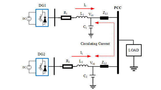
Figure 1: Circulating current flow between DGs due to different values of line impedance
As established, DG source inputs can come from wind, solar, and electric vehicles, or from battery storages with intermittent power ratings. As for the localized microgrid system, the impact of the circulating current is severe, especially on the voltage, phase, and frequency at the inverter outputs. The main problem that arises when generating the circulating current at the inverter output is that when the type of line impedance is different, such as in resistive impedance or inductive impedance, that will create different amounts of circulating current and new paths of current flows. When this happens, it can reduce the efficiency of the line connection between the inverter at the point of common coupling (PCC). Imagine a scenario in which there are ‘N’ inverters connected to the PCC with different line impedance: the circulating current will severely damage the system. The circulating current will flow from the highest inverter voltage to the lowest inverter voltage, which will destroy the accurate power sharing between the inverters. Therefore, the droop control is suitable when the type of impedances of the DGs are the same value and type. When the impedance and types are different, the droop control is less efficient, so an improvement of the droop control is necessary. This can be done by adding the virtual impedance, establishing a solution for circulating current, and for accurate power sharing. When a microgrid consists of large local loads and large line impedance, the DG inverter will also face a voltage deviation issue, which causes an increase in the circulating currents, as well as power-sharing issues. Several solutions can be employed in this situation. One solution is angle droop control, which deals with the stability and power-sharing performance in the inverter-based microgrid system and, with frequency droop, can control this issue. Frequency variation with the conventional power frequency droop control technique is higher than the angle droop control technique. The transient response of the system also improves with angle droop control. For voltage regulation, the Q-U droop control is utilized to ensure a fixed voltage at the inverter’s output. The advantage of the Q-U dot droop technique is that it shows superior behavior regardless of the grid impedance. Moreover, in order to suppress the circulating current, a multi-loop control mechanism for parallel inverters control can also be implemented. This will improve system reliability and adaptability by combining the droop control and the outer loop controller with the voltage and current control as the inner loop controls.
At the end of this technique, the circulating current due to different rated power at the DGs’ input can be solved by introducing the improved droop control, which, embedded with virtual impedance control in order to make the reference signal from the droop control, is also contributed by the line impedance in the decentralized topology system.
For smooth operation and proper power sharing among DG inverters, a reliable, fast, and effective circulating current suppression technique that does not compromise the output voltage, frequency and current is indispensable. This is essential in ensuring the DGs can dominate the electrical grid in the future.
To view all articles in this issue, please go to November 2023 eNewsletter. For a downloadable copy, please visit the IEEE Smart Cities Resource Center.


To have the Bulletin delivered monthly to your inbox, join the IEEE Smart Grid Community.
Past Issues
To view archived articles, and issues, which deliver rich insight into the forces shaping the future of the smart grid. Older Bulletins (formerly eNewsletter) can be found here. To download full issues, visit the publications section of the IEEE Smart Grid Resource Center.
IEEE Smart Grid Bulletin Editors

Managing Editor

Assistant Managing Editor

Interim Managing Editor
IEEE Smart Grid Publications Editorial Board
Mehdi Moghadasi
Mehmet Cintuglu
Geev Mokryani
Jose Medina
Merhrdad Boloorchi
Vigna Kumaran
Hossam Gaber
Jorge Angarita
Ali Nabavi
Vijay Sood
Julio Usaola
Cesar Duarte
Gabriel Ordoñez
Jorge Martinez
Jenny Zhou
Click here for more info
Dr. Panayiotis (Panos) Moutis
Editor-in-Chief
IEEE Smart Grid Bulletin